Introduction
Measuring the current that flows through a sense resistor seems easy. Amplify the voltage, read it with an ADC, and now you know what the current is. However, it gets more difficult if the sense resistor sits at a voltage that is very different from system ground. The typical solutions that bridge that voltage differ in either the analog or digital domain. But here is a different approach—wireless.
Analog current sense ICs are compact solutions. However, the voltage difference that they can withstand is limited by semiconductor processes. It is difficult to find devices that are rated for more than 100 V, and these circuits often lose accuracy if the sense resistor’s common-mode voltage changes quickly or swings both above and below system ground.
Digital isolation techniques (magnetic or optical) are a bit more bulky, but work without loss of accuracy and can typically withstand thousands of volts. These circuits need an isolated power supply, but that can sometimes be integrated in the isolator component. If the sense resistor is physically separated from the main system, then you also may need to run long wires or cables.
A wireless current sense circuit overcomes many of these limitations. By allowing the entire circuit to float with the common mode of the sense resistor and transmitting the measured data wirelessly over the air, there are no voltage limitations at all. The sense resistor can be located anywhere without the need to run cables. If the circuit is very low power, then you don’t even need an isolated power supply and can instead run for many years on a small battery.
Design Overview
Figure 1 shows the block diagram of the design. The current sense circuit is based on the LTC2063 chopper-stabilized op amp to amplify the voltage drop across a sense resistor. The micropower SAR ADC AD7988 digitizes the value and reports the result via an SPI interface. The LTP5901-IPM is the radio module that contains not only the radio, but also the networking firmware needed to automatically form an IP-based mesh network. In addition, the LTP5901-IPM has a built-in microprocessor that reads the AD7988 ADC SPI port. The LTC3335 is a low power, dc-to-dc power supply that converts the battery voltage to a constant output voltage. The LTC3335 also includes a coulomb counter that reports the cumulative charge pulled from the battery.
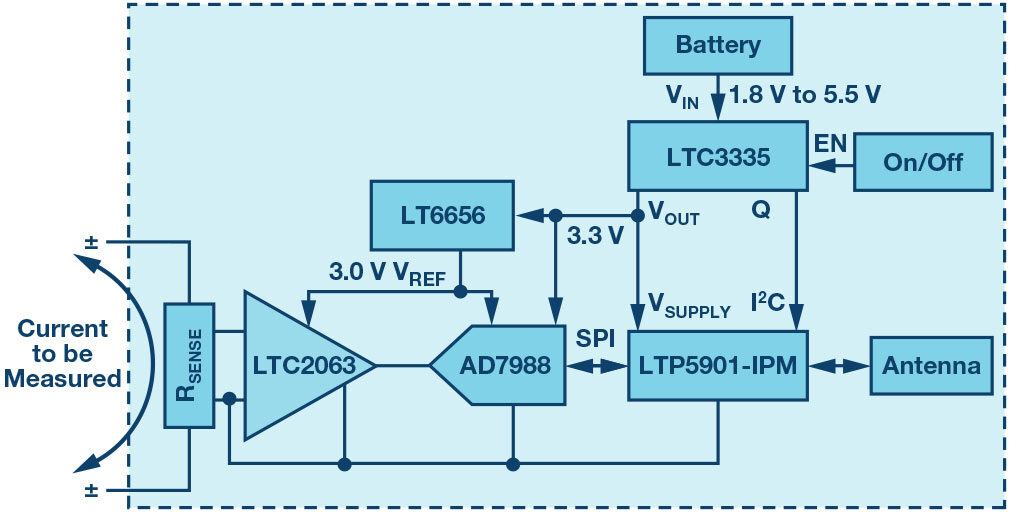
figure 1. A low power, wireless current sense circuit is formed by a low power chopper op amp to amplify the sense voltage. It is digitized using a low power ADC and reference and connected to a SmartMesh IP wireless radio module. A low power, dc-to-dc converter conditions the battery and also keeps track of the charge drawn from the battery.
Signal Chain
The LTC2063 is an ultralow power, chopper-stabilized op amp. With a maximum supply current of 2 µA, it is uniquely suited for use in battery powered applications. Because the offset voltage is less than 10 µV, it can measure very small voltage drops without loss of accuracy. Figure 2 shows the LTC2063 configured to gain up and level shift the voltage across a 10 mΩ sense resistor. The gain is chosen so that the ±10 mV full-scale input at the sense resistor (corresponding to ±1 A of current) maps to a near full-scale range at the output, centered around 1.5 V. This amplified signal is fed into a 16-bit SAR ADC. The AD7988 was chosen for its very low standby current and good dc accuracy. At low sample rates, the ADC automatically shuts down in between conversions, resulting in an average current consumption of as little as 10 µA at 1 kSPS. The LT6656 biases the amplifier, the level-shift resistors, and the ADC’s reference input. The LT6656 voltage reference consumes less than 1 µA and can drive up to 5 mA loads with low dropout, making it easy to output a precise 3 V, even when powered from the 3.3 V system supply.
There are three roughly equal sources to offset error in this signal chain, together contributing about 0.5% relative to a ±10 mV full-scale input. They are the offset voltage of the LTC2063 and AD7988, as well as mismatch in the level-shift resistors (0.1% resistors are recommended). A one-point calibration step could largely eliminate that offset. Gain error is generally dominated by inaccuracies in available sense resistors, which tend to be worse than the 0.05%, 10 ppm/°C specifications of the LT6656 voltage reference.
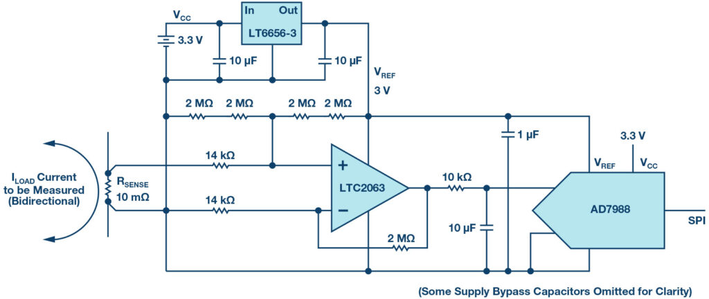
Figure 2. The current sense circuitry floats with the sense resistor voltage. The LTC2063 chopper op amp amplifies the sense voltage and biases it mid-rail for the AD7988 ADC. The LT6656-3 provides the precision 3 V reference.
Power Management
The LTC3335 is a nanopower buck-boost converter with an integrated coulomb counter. It is configured to provide a regulated 3.3 V output from an input supply between 1.8 V and 5.5 V. This allows the circuit to be powered by two Alkaline primary battery cells. For duty-cycled wireless applications, the load current can easily vary from 1 µA to 20 mA, depending on whether the radio is in active or sleep mode. The LTC3335 has a quiescent current of just 680 nA at no load, which keeps the entire circuit operating at very low power when the radio and signal chain are in sleep mode. Still, the LTC3335 can output as much as 50 mA, which easily provides enough power during radio transmit/receive and for a variety of signal chain circuits.
The LTC3335 also has a handy, built-in coulomb counter. When switching, it keeps track of the total charge that it draws from the battery. This information can be read out using an I2C interface and can then be used as a predictor for when it may become time to replace the batteries.
Wireless Networking
The LTP5901-IPM is a complete wireless radio module that includes the radio transceiver, embedded microprocessor, and SmartMesh IP networking software. The LTP5901-IPM performs two functions in this application: wireless networking and housekeeping functions (processes). When multiple SmartMesh IP motes are powered up in the vicinity of a network manager, the motes automatically recognize each other and form a wireless mesh network. The entire network is automatically time-synchronized, which means that each radio is only powered on during very short, specific time intervals. As a result, each node can function not only as a source of sensor information, but also as a routing node to relay data from other nodes toward the manager. This creates a highly reliable, low power mesh network where multiple paths are available from each node to the manager, even though all nodes, including the routing nodes, operate on very low power.
The LTP5901-IPM includes an ARM® Cortex®-M3 microprocessor core that runs the networking software. In addition, users may write application firmware to perform tasks specific to the user application. In this example, the microprocessor inside the LTP5901-IPM reads the SPI port of the current measurement ADC (AD7988) and reads the I2C port of the coulomb counter (LTC3335). The microprocessor can also put the chopper op amp (LTC2063) in shutdown mode, further reducing its current consumption from 2 µA to 200 nA. This provides additional power savings in use models with extremely long intervals between measurements.
Overall Power Consumption
The total power consumption of the complete application circuit depends on various factors, including how often the signal chain takes a reading and how the nodes are configured in the network. Typical power consumption for a mote reporting once per second is less than 5 µA for the measurement circuit and can be 40 µA for the wireless radio, allowing years of operation on small batteries.
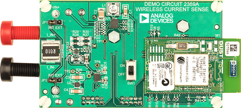
Figure 3. A complete wireless current sense circuit is implemented on a small PCB. The only physical connections are the banana jacks for the current to be measured. The wireless radio module is shown on the right. The circuit is powered from two AAA batteries connected on the back of the board.
Conclusion
Combining Linear Technology and Analog Devices signal chain, power management, and wireless networking products enables the design of a truly wireless current sense circuit. Figure 3 shows an example implementation. The new ultralow power LTC2063 chopper op amp can accurately read small voltage drops across a sense resistor. The entire circuit, including the micropower ADC and voltage reference, floats with the common mode of the sense resistor. The nanopower LTC3335 switcher can power the circuit for years from a small battery, while reporting cumulative battery usage with its built-in coulomb counter. The LTP5901-IPM wireless module manages the entire application and automatically connects to a highly reliable SmartMesh IP network.
Kris Lokere is a strategic applications manager for signal chain products, joining ADI as part of the merger with Linear Technology. Kris enjoys architecting systems that combine technologies from multiple product lines. In the past 20 years, Kris has designed op amps, built engineering teams, and managed product line strategy. Kris holds multiple patents and received an M.S.E.E. degree from Katholieke Universiteit Leuven and an M.B.A. from Babson College.