Introduction
Knowing the pH value of a liquid is essential in many industries. Nearly every industry that handles liquids needs a measurement system for pH. Obviously, it is important for waste water systems and waste water plants, but did you know that the water from a brewery needs to have a special pH value before it reaches the sewage water system? This design tip is intended to help adding high precision isolation to water treatment systems.
This article discusses the addition of high precision isolation to a system. This is essential for monitoring water pH that is located far from the system, monitoring differing ground levels, or for protecting a system from high voltage when an error occurs.
The pH value is a measure of the acidity or basicity of an aqueous solution. It is a unitless number and is defined as the negative common logarithm of the hydrogen ion activity according to the following equation:
Pure water is defined as having a pH value of 7, while acids have values of less than 7 and bases have values above 7. So-called indicators that change colour according to the pH value are often used for measuring the pH. However, this measurement only provides a rough estimate. The circuit shown in Figure 1 is intended for evaluation of combined glass electrodes. It has an accuracy of 0.5% for the pH range from 0 to 14 and is temperature compensated. The circuit supports a large range of pH sensors, which can have high impedance values from 1MΩ to a few GΩ.
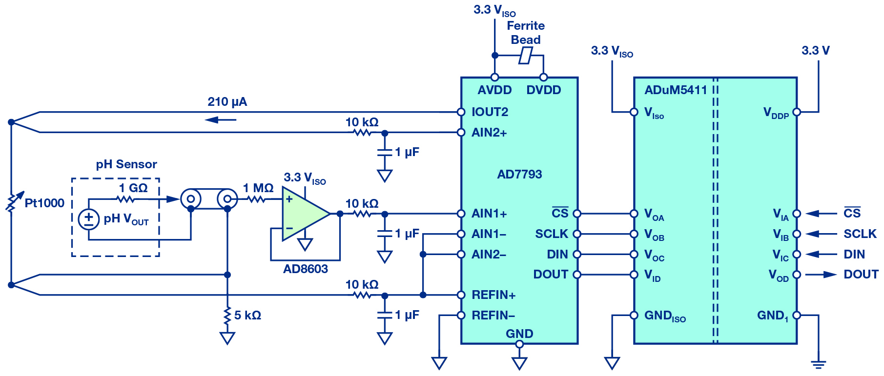
Figure 1. pH sensor circuit with combined electrode (simplified).
The pH Electrode
The pH probe consists of a measuring electrode and a reference electrode, which is comparable to a battery. If the probe is dipped into a test solution, the measurement electrode generates a voltage depending on the hydrogen ion activity. A typical output value is 59.14mV per unit of pH at 25°C. Due to the temperature dependency, this value can rise to 70mV/pH. This voltage is compared with the reference electrode. If the test solution is acidic (low pH), the potential at the probe output is greater than 0; for a basic solution, it is less than 0. The output value can be calculated using the following equation:
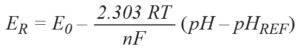
where:
E is the output voltage of the probe.
E0 is the standard electrode potential (typically 0V), dependent on the probe. R is the universal gas constant. R = 8.31447 J mol−1 K−1.
T is the temperature in Kelvin.
n is the number of transferred electrons (or equivalent number). F is the Faraday constant. F = 96485.34 C mol−1.
pH is the hydrogen ion concentration of unknown solution. pHREF = 7, reference value of reference electrode.
The Circuit
The three main elements of the circuit are the buffer for the probe, the ADC, and the isolator with the voltage transmission. The buffer op amp AD8603 was selected because it has low power consumption, low noise, and extremely low input bias current. The low input bias current of typically 200fA ensures that the voltage drop due to current flow across the internal resistor of the probe is minimised. Another important component is the ADC, represented here by the AD7793, a 24-bit ∑-Δ converter with an integrated power source and programmable amplifier. The integrated current source generates the current that flows through the Pt1000. With this, the temperature measurement needed for compensation in the processor is performed. The same current also flows through the 5kΩ resistor (0.1% tolerance), which thereby generates the reference voltage of 1.05V. As a second function, the resistor boosts the common-mode voltage. Through this and through selection of the reference voltage, the input range of the ADC is fully utilised: the probe outputs ±414mV – a maximum ±490mV. The isolator is the ADuM5411, an isolated dc-to-dc converter that simultaneously provides for isolation of the SPI interface of the ADC.
Circuit Characteristics
To achieve high accuracy, the op amp was selected with a typical input bias current of 200fA, which leads to a maximum voltage offset of 0.2mV at the probe impedance of 1GΩ. This corresponds to an error of 0.0037 units of pH at 25°C. Even with a maximum input bias current of 1pA, the maximum offset error is very low, at 1mV. In order not to give away this good starting position, it is advisable to take suitable layout measurements by using, for example, a guard ring, shielding, and other techniques that are not affected by very low currents. At the selected data rate of 16.7Hz and a gain of 1, the noise generated by the ADC is approximately 2µVrms. If the calculation is done with a peak-to-peak noise of 13µV, the accuracy of the pH value is 0.00022 units of pH. If the noise from the amplifier and the noise from the ADC are taken together, this yields 0.00053 units of pH – and, hence, the offset error is much more significant.
Conclusion
The circuit shown here is a simple, very precise, and power-saving variant for pH sensor readings. Once the circuit has been calibrated, an accuracy of 0.5%, corresponding to 0.005 units of pH can be achieved. Thanks to the isolation, it is suitable for numerous applications.
About the Author
Thomas Tzscheetzsch joined Analog Devices in 2010, working as a senior field applications engineer. From 2010 to 2012, he covered the regional customer base in the middle of Germany and, since 2012, has been working in a key account team with a smaller customer base. After the reorganization in 2017, he’s leading a team of FAEs in the IHC cluster in CE countries as FAE manager. He can be reached at thomas.tzscheetzsch@analog.com.